
Version 1.0 (draft) · Public domain (CC0 1.0)
All dimensions are in millimetres. "Clearance" means the fit clearance, 0.2 mm by default, which a maker may change for their printer. The words must, should and may mean what they usually mean in standards: must is required for compatibility, should is strongly recommended, may is optional. The reference implementation is public/js/geometry/morph.js; where this document and the code disagree, report it (see Contributing).
1. Coordinates
- X runs left to right along a wall or desk, Y runs away from the wall (towards the viewer), Z runs up.
- A tile's front face is the face you see. Its back faces the wall.
- A node is a point on the grid where a socket sits.
2. The grid
| Property | Value |
|---|---|
| Pitch (node to node) | 30 in X and in Y |
| First node | 15 from the tile's left and bottom edges |
| Accessory width | n × 30 − 1 (0.5 gap each side to the next accessory), n ≥ 1 |
| Desk Pod width | n × 30 − 0.4, 2 ≤ n ≤ 8 |
Everything must place its sockets on node positions, so a part can move anywhere on the grid in 30 mm steps.
3. The twist-lock socket and pin
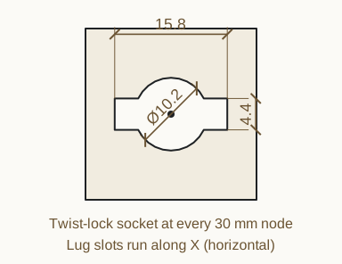
3.1 Socket
| Property | Value |
|---|---|
| Round hole | Ø 10.2 (radius 5.1) |
| Lug slots | two, opposite each other, 4.4 wide, reaching 7.9 from the centre (15.8 tip to tip) |
| Slot direction | along X (horizontal) on tiles and back plates |
| Where | at every node of a tile, and at the mounting nodes of every accessory back plate |
The socket is the same through the tile (5 thick) and through an accessory back plate (3.2 thick), so one pin passes through both.
3.2 Pin
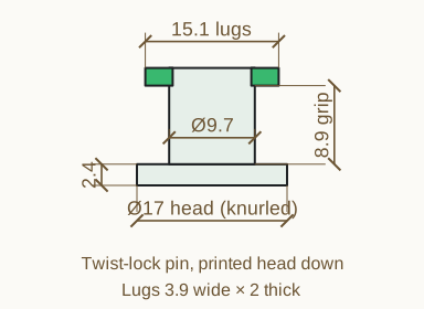
| Property | Value |
|---|---|
| Head | Ø 17, 2.4 thick, knurled edge (48 teeth, 0.6 deep) for grip |
| Shaft | Ø 9.7 (radius 4.85, 0.25 under the hole) |
| Grip length (head to lugs) | back plate + tile + 2 × clearance + 0.3; 8.9 for a 3.2 plate, a 5 tile and 0.2 clearance |
| Lugs | two, opposite, 3.9 wide, 2 thick, reaching 7.55 from the centre (15.1 tip to tip) |
| Overall length | 13.3 at default sizes |
| Print orientation | head down, no supports |
3.3 How it locks
- Line the lugs up with the slots in the accessory and the tile behind it.
- Push the pin through. The lugs come out behind the tile into the standoff space (§4.2).
- Turn the pin a quarter turn. The lugs now bear on the back of the tile and the accessory is clamped between the pin head and the tile.
A compatible pin must fit a socket with the default clearance. Version 1.0 has no detent at the locked position; the clamp holds by the head and lugs gripping the stack.
4. Tiles
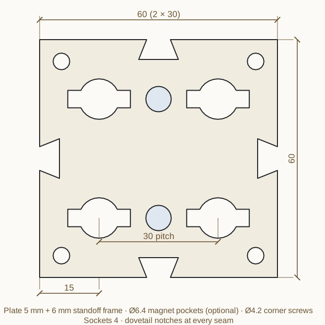
4.1 Plate
| Property | Value |
|---|---|
| Size | cols × 30 by rows × 30, 1 to 8 nodes each way (a 256 mm bed fits 8 × 8) |
| Thickness | 5 |
| Sockets | one at every node (§3.1) |
| Corner screws | four, Ø 4.2, about 5.5 from each edge, for 3.5 to 4 mm wood screws |
| Edge notches | a dovetail notch at every seam between nodes on every edge (§5) |
| Lattice | optional, kept out of an edge band (notch depth + rib + 1.5) and at least 7.9 + rib + 1.2 from every socket centre |
| Print orientation | front face down on the bed, no supports |
4.2 Standoff
A frame on the back holds the plate 6 off the wall so the pin lugs have room to turn.
| Property | Value |
|---|---|
| Frame height | 6 behind the plate (tile is 11 deep overall) |
| Frame width | 2.4 |
| Frame position | inset 5.6 from the outside edge, inside the notch band |
5. Connector keys
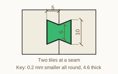
Two tiles join with a bow-tie key that drops into the notches on either side of a seam.
| Property | Notch (in each tile) | Key |
|---|---|---|
| Depth from the seam | 5 | 5 − clearance each side |
| Width at the seam | 6 | 6 − 2 × clearance |
| Width at the inner end | 10 | 10 − 2 × clearance |
| Thickness | through the plate (5) | 4.6 (plate − 0.4) |
Keys should be printed flat in the accent colour. A tile of cols × rows nodes has 2 × (cols − 1 + rows − 1) notches, one pair per shared seam.
6. Magnets
Magnets are optional, for parts that lift off. Use 6 × 2 mm neodymium discs.
| Property | Value |
|---|---|
| Ø 6.4, 2.2 deep, blind | |
| On tiles | midway between two nodes in X (a node's X + 15), pocket open on the front face |
| On accessory back plates | at each mounting node's X + 15 when that fits (at least 5 from the edge), otherwise at the node; pocket open on the wall side, hidden from the front |
| Pocket depth on a thin plate | the smaller of 2.2 and plate thickness − 0.8 |
Mind the polarity: glue every tile magnet with the same face out, and every accessory magnet the opposite way.
7. Accessories
7.1 Back plate
Every wall accessory has a back plate that mounts on the grid.
| Property | Value |
|---|---|
| Thickness | 3.2 |
| Width | n × 30 − 1 |
| Height | at least 30 |
| Mounting | pins, magnets, both, or none (freestanding) |
| Socket columns | round(width ÷ 30), centred |
| Socket rows | one row 15 below the top; parts 90 or taller add a second row a whole number of 30 mm steps lower, so both rows land on nodes |
| Screw holes (Paddock Aura) | Ø 4.2, 4.5 in from the top corners, exposed as a detail |
7.2 Accessory types in version 1.0
| Accessory | Notes |
|---|---|
| Drop-in bin | width n × 30 − 1, any depth and height ≥ 20; skeleton, solid or Galley shell walls; Paddock blowout vents, Studio cable slot |
| Shelf | lattice or solid deck, front lip, two gussets |
| Tool hook | one node wide, two nodes tall, reach 15 to 150 |
| Tool tray | pockets shaped from traced tools, freestanding or wall-mounted |
Other accessories are welcome. A compatible accessory must use the back plate in §7.1, or mount through sockets that match §3.1 at node positions.
8. The Desk Pod
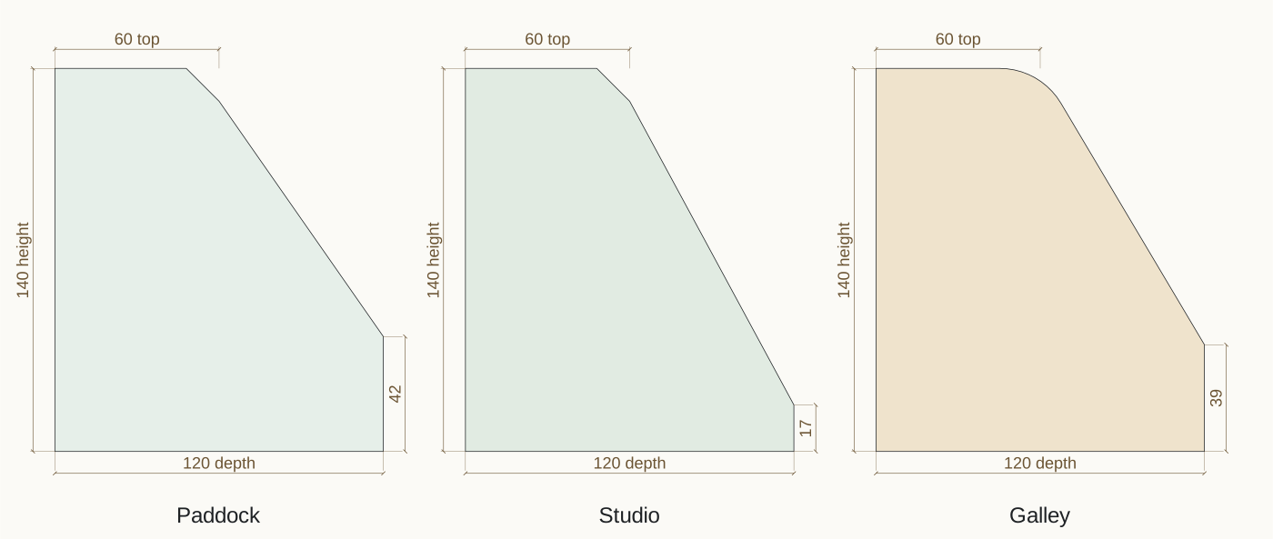
A freestanding desk unit whose front leans back. It prints in parts so that no part needs supports.
8.1 Size and profile
| Property | Value |
|---|---|
| Width | n × 30 − 0.4, n from 2 to 8 (default 4, 119.6) |
| Depth | 60 to 220 (default 120) |
| Height | 70 to 260 (default 140) |
| Top depth | half the depth |
| Front lip height | Paddock max(24, 0.30 × height); Studio max(16, 0.12 × height); Galley max(24, 0.28 × height) |
| Top front edge | Paddock and Studio: a chamfer of min(12, top depth ÷ 4); Galley: a round of min(26, 0.45 × top depth, 0.35 × (height − lip)) |
| Walls | at least 2 (engine wall thickness, §9); Galley 2.4; back plate 3.2 when wall-mounted |
The profile is: back edge straight up, flat top, the chamfer or round, the leaning front down to the lip, the vertical lip, and the floor.
8.2 Parts and print orientation
| Part | Colour | Printed |
|---|---|---|
| Sleeve (floor, back, top, front in one piece) | body | standing on one end: every wall is vertical |
| Side panels (two), or one side panel and a link frame | body | flat, plug up |
| Faceplate (Studio organiser or pen rack) | accent | face down |
| Window clips (Studio window, four) | accent | flat, peg up |
| Dividers (Paddock, 0 to 6) | accent | flat |
| Link keys (two, when linking) | accent | flat |
| Twist-lock pins (when wall-mounted) | accent | head down |
The sleeve prints on a small footprint (its wall edges only), so a brim is recommended.
8.3 Side panels and the plug
| Property | Value |
|---|---|
| Panel thickness | 3 |
| Plug | a ring 4 deep and 1.6 wide on the inside face, following the profile inset by the wall thickness + 0.2 |
| Plug bottom | stops at 6.7 above the floor, clear of the end rails |
| Link-key cut-outs | 11.2 wide × 5.3 tall at the bottom edge, under each link-key notch |
8.4 Linking pods
| Property | Value |
|---|---|
| End rails | 10 wide × 6.5 tall along the floor at each end of the sleeve |
| Link-key notches | dovetail (as §5: 5 deep, 6 at the mouth, 10 inside), 5.3 tall, cut into the rails from underneath at 30% and 70% of the depth, at both ends |
| Link frame | a ring that plugs 4 into each pod, with a 3 flange between them (11 overall) |
| Link key | a dovetail at each end joined by a 3 bridge, 4.8 thick, clearance all round |
8.5 Studio front
| Property | Value |
|---|---|
| Opening | inset 16 from each end and 10 from the top and bottom of the leaning face |
| Face thickness | max(wall, 2.4) |
| Ledge | a ring behind the face, 1.5 inside the opening, 1.6 deep; the faceplate or sheet rests on it and the lean holds it in |
| Faceplate | opening − 0.25 each side, 2.4 thick, with pockets that each have a 1.2 wall and 1.2 floor |
| SD card slot | 25 × 2.6, 16 deep, rows 8 apart, columns 29 apart |
| microSD slot | 11.6 × 1.4, 9 deep, rows 5.5 apart, columns 15 apart |
| Pen channel | 11 wide, the full height of the faceplate, 14 deep, 14.6 apart |
| Window sheet | 2 thick, opening − 0.4 each way (the generator shows the size to cut) |
| Window clip | a 15 × 7 × 1.6 tab with a Ø3.3 peg that presses into a Ø3.2 hole, 6.5 outside the opening at 30% and 70% of its height, both sides |
8.6 Paddock dividers and Galley shelf
| Property | Value |
|---|---|
| Divider | 2.4 thick, the profile inset by the wall thickness + 0.8, lattice |
| Divider slot | two rails 1.2 wide, 4 tall, 2.9 apart, along the floor and up the back to 70% of the height, spaced evenly across the width |
| Galley shelf | 3 thick with a rounded nose, at lip + 0.42 × (height − lip), stopping 10 short of the front |
| Galley coves | 8 radius where the floor meets the back and the lip |
8.7 Side sockets
Both side panels are MotiveMesh surfaces, so hooks, hangers, bins and shelves lock onto the sides of a pod with standard pins.
| Property | Value |
|---|---|
| Sockets | as §3.1, slots horizontal, on a 30 grid in both directions |
| Where | as many nodes as fit inside the plug ring with a boss's clearance; the grid is shifted in 2 mm steps to fit the most |
| Boss | a ring on the inside face around each socket, radius 9.55 (lug reach + 2), 2 tall, so panel + boss = 5, the tile thickness |
| Room for the lugs | nothing inside the pod comes closer than 5.5 to the side panel's inner face (the Galley shelf and coves stop short) |
| Count | 10 to 12 a side at the default size; 2 or more at the smallest |
| Optional | a pod can be made with plain sides |
Accessories made to §7.1 fit the side sockets directly: an accessory's top socket row and 30 mm columns land on the side grid.
8.8 On the wall
With mounting set to pins or magnets, the back becomes a back plate (§7.1) and the pod hangs on MotiveMesh like any accessory.
9. Material-aware building
Each part is built for the filament it will be printed in.
9.1 Filament profiles
| Filament | Density g/cm³ | Strength | Stiffness | Heat °C | Skeleton |
|---|---|---|---|---|---|
| PLA | 1.24 | 1.00 | 1.00 | 55 | no |
| PETG | 1.27 | 0.95 | 0.80 | 70 | no |
| ASA | 1.07 | 1.05 | 0.90 | 95 | yes |
| ABS | 1.04 | 0.95 | 0.85 | 90 | yes |
| PETG-CF | 1.29 | 1.20 | 1.50 | 75 | yes |
| PA-CF (nylon) | 1.15 | 1.60 | 1.80 | 120 | yes |
| TPU 95A | 1.21 | 0.50 | 0.10 | 60 | no |
Strength and stiffness are relative to PLA and are planning figures, not test data. These seven are the reference profiles; the generator knows every FDM filament family and its common variants (66 at the time of writing, from PLA to PEEK), listed with the same fields in public/js/filaments.js and at vertex.mintmotive.com.au/filaments. The rules below apply to all of them.
9.2 Build mode
- Shell in the Galley Aura, whatever the filament.
- Skeleton when the filament's profile says so, or when the maker asks for it.
- Solid otherwise, or when the maker asks for it.
9.3 Sizes the engine derives
| Size | Rule |
|---|---|
| Skeleton wall | clamp(2 ÷ stiffness^0.3, 1.6, 2.6) |
| Solid wall | clamp(1.6 ÷ √stiffness, 1.2, 2.4) |
| Shell (Galley bins) | two 1.0 skins, 1.8 apart, joined by hidden ribs about every 16 |
| Lattice rib | clamp(1.4 × √(1.1 ÷ strength), 1.0, 2.2) |
| Lattice cell | clamp(12 × √strength, 9, 18) |
| Floor | 1.6 skeleton, 1.4 otherwise |
Which gives:
| Filament | Mode (Paddock) | Wall | Rib | Cell |
|---|---|---|---|---|
| PLA | solid | 1.6 | 1.5 | 12 |
| PETG | solid | 1.8 | 1.5 | 11.7 |
| ASA | skeleton | 2.1 | 1.4 | 12.3 |
| ABS | skeleton | 2.1 | 1.5 | 11.7 |
| PETG-CF | skeleton | 1.8 | 1.3 | 13.1 |
| PA-CF | skeleton | 1.7 | 1.2 | 15.2 |
| TPU 95A | solid | 2.4 | 2.1 | 9 |
9.4 Lattice patterns
| Pattern | Shape | Why |
|---|---|---|
| Isogrid | equilateral triangles side 1.25 × cell, shrunk so a rib runs between them | stiff in every direction |
| Honeycomb | pointy-top hexagons, pitch = cell | pointed tops print cleanly upright |
| Diamond | squares turned 45° | every edge at 45°, prints in any orientation |
| Slots | full-height flutes, 0.5 × cell wide, rounded ends | calm vertical lines for the Studio |
Lattice holes must stay clear of sockets, magnet pockets, edges and joints by at least one rib plus the margins given in each section.
9.5 The report
The generator reports, for every part, against the same part built solid in PLA:
- plastic in grams (volume × density);
- a rough print time (a planning figure, not a slicer estimate);
- relative stiffness, where solid PLA is 100: 100 × stiffness × (effective wall ÷ 1.6) × (1 − 0.45 × open fraction). The Galley shell counts as a sandwich panel.
10. Conformance
A part is MotiveMesh compatible when:
- its sockets match §3.1 and sit on 30 mm nodes (§2), or it mounts with pins that match §3.2;
- its back plate matches §7.1, or it is a tile that matches §4 and §5;
- its magnet pockets, if any, match §6;
- it prints without supports in the orientation it is published in;
- its published description says which filament it was designed for.
Parts that meet this list may be called "MotiveMesh compatible" by anyone. No permission is needed.